Footings - Design
Spread Footing Definitions Spreadsheet
Footing General Properties
The General tab contains material properties and other toggles specific to footing design discussed below.

Click on image to enlarge it
Reinforcement Ratios
Acceptable steel ratios are controlled by ACI 318-14 Section 24.4.3 (ACI 318-11 Section 7.12.2.1) which stipulates that the minimum steel ratio for Grade 40 or 50 steel is .0020. For Grade 60, the ratio is 0.0018. The ratio cannot be less than 0.0014 for any grade of steel.
ACI 318-11 Section 7.12 explicitly states “gross concrete area” is to be used. Thus, for this and earlier versions of the code, RISA requires that the entire cross-section (top and bottom reinforcement together) meets this requirement.
For the ACI 318-14 code, the flexural minimum section has been updated to require this area of steel in each face where flexural steel exists. Therefore, for this version of the code, RISA enforces this minimum for each face individually. See ACI 318-14 Sections 8.6.1.1 and 7.6.1.1 for more information.
In addition, the codes limit the maximum steel that can be used. The 1995 and 1999 codes limit the steel ratio to 75% of the balanced condition. The 2002 and newer codes instead limit the minimum strain on the reinforcing steel to 0.004. RISAFoundation doesn't specifically enforce these maximums and instead relies on this Max Steel Ratio separately for each face.
Material
This allows you to select the material from the definitions contained in the Materials Spreadsheet.
Design Rules
This allows you to select the design rule from those defined in the Design Rules Spreadsheet.
Equal Bar Spacing
Checking the Equal Bar Spacing option indicates that you do not want to specify banded reinforcement. If you check this box, RISAFoundation will determine the tightest spacing required per ACI 318-14 Section 13.3.3.3 (ACI 318-11 Section 15.4.4) and then use that spacing throughout the footing.
Enveloping Multiple Footing Designs
Checking the box in the Group Design column will cause all footings assigned to the current footing definition to use the same final size. The largest required size within the group of footings will be used for all footings within the group. The maximum required reinforcement for the footings and pedestals will also be enveloped.
Concrete Bearing Check
Checking the box in the Concrete Bearing column will force the program to check the concrete bearing failure between the footing and pedestal.
Force Top Bars
The Force Top Bars option allows the user to indicate that top bars are required for this footing, even for cases where the footing does not experience significant uplift or negative moment. One reason for checking this box would be to spread out the Temperature / Shrinkage reinforcement between the top and bottom layers of steel.
Footing Geometry
The Geometry tab contains the basic information that controls the size and thickness of the footing.

Click on image to enlarge it
These parameters define the minimum and maximum length, width and thickness for the footing. When RISAFoundation sizes the footing, it optimizes for the smallest footing that fits within the parameters and does not exceed the allowable soil bearing pressure. RISAFoundation favors footings with the lowest length/width ratio (as close to a square as possible).
If you are investigating an existing footing size that you don't want RISAFoundation to change, you may either specify the same maximum and minimum length, width and/or thickness OR specify the maximum values and set the design increments to zero.
Force Footing to be Square
Checking the box in the Force Square column will restrict the design to square footings only.
Footing Pedestal
The Pedestal tab contains the basic information that will control the width and height of the pedestal. It will also control the location of the pedestal if you have an eccentric footing.

Click on image to enlarge it
The pedestal geometry is entered in these fields. The type can be specified as either a pedestal or post. Select the  (ellipsis) button in the Shape cell to prompt the following dialog box where you can specify the dimensions of the pedestal:

Click on image to enlarge it
The height is the distance from the upper surface of the footing to the top of the pedestal. The pedestal location may be controlled, as discussed in the Boundaries and Eccentricities section below.
Boundaries and Eccentricities
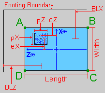
When specifying an eccentric pedestal, the eX and eZ values are the offsets from the center of the footing in the local X and Z directions, respectively. These values may be either positive or negative.
You may use the BLx or BLz entries to set boundary lines for the footing in one or two directions, or you may specify the pedestal eccentricity from the centroid of the footing. If you set boundary lines, RISAFoundation will keep the sides of the footing from violating the boundary. These values may be either positive or negative.
Click on image to enlarge it
Soil Properties
The Soil Properties tab contains the basic information related to design for soil bearing.

Click on image to enlarge it
Overburden
Overburden is the weight of soil or other dead loads (e.g. pavement) which exist above the footing in its final (constructed) condition. RISAFoundation applies the overburden pressure uniformly on the footing, except at the pedestal footprint.
Passive Resistance of Soil
For additional sliding resistance, you may enter the passive resistance of the soil as a lump sum value. RISAFoundation applies this value in both directions.
Coefficient of Friction
RISAFoundation multiplies this coefficient of friction by the total vertical forces to determine the soil sliding resistance.
Gross/Net
In RISAFoundation, the Allowable Soil Bearing value is controlled by the Soil Region. By default, this value is always taken as a Gross allowable soil pressure.
Allowable Soil Bearing values are typically supplied by the Geotechnical Engineer as either Gross or Net allowable values. The soil bearing check uses the same load to check soil bearing (Footing Self Weight + Overburden + Applied Load), regardless of whether Gross or Net is specified.
When a Gross soil pressure is specified, the load is compared directly against the Bearing Allowable (user-entered).
When a Net soil pressure is specified, the load is compared against a modified soil capacity, as shown below:
Soil Capacity = Bearing Allowable (user-entered) + Footing Self Weight + Overburden (user-entered).
If the sum of Footing Self Weight and Overburden does not equal the soil weight, which was present above the footing/soil interface strata prior to excavation, then the modified soil capacity provided by the program is incorrect. In this circumstance, the Net Allowable Soil Bearing value should be specified as a Gross value in the program, and the magnitude of Bearing Allowable should be increased by that pre-excavation soil weight.
Local Axes
The “A,B,C,D” notation provides a local reference system for the footing. The local z-axis is defined as positive from B towards A, and the local x-axis is defined as positive from D towards A. The origin for the local axes is the geometric center of the footing.
Click on image to enlarge it
It is important to realize that the local footing axes do NOT necessarily correspond to the Global axes of the RISA model or the local axes of the column member.
Limitations
Non-Linear Effects
The Node Reaction results can differ from the design results used for the OTM safety factor calculation. The reason for this is that the OTM safety factor needs to determine whether each component (P, V or M) of each load creates a stabilizing or destabilizing moment.